A. Choosing Power Wire Wound Resistors and parameters determination :
1. resistor power Power W=I^2*R where :
W = Resistor Power I = maximum loading current
R = rated resistance value or maximum resistance of Power Resistor
2. Never over load the resistor beyond the specified voltage, rated power and loading current.
3. We recommend choosing a resistor with a rated power of at least 1.3 to 4 times higher than the actual required loading power if your application requires the resistor to run continuously for 100% duty cycle. This can extend the resistor’s service life and lower it’s surface temperature.
4. If the maximum or surge power larger than the rated resistor power, please tell the actual working condition like peak / surge voltage, resistance value, duty cycle, loading time and repetition rate.
5. For Surge Voltage application, if loading Voltage is larger than the rated Voltage according to resistor rated Power and Resistance value, please tell us the Peak to Peak Voltage range, Duty Cycle, Repetition Rate per unit time or Frequency and loading time.
6. Our resistor can withstand 5-10 times of the rated power for 5 seconds, depending on the current pulse width, resistor series and cooling system.
7. For very low ohmic Power Resistor, it is better to tell the working Voltage, Loading Time and Duty Cycle of your application. As different Voltage can induce different resistor current. In turn different raw materials and production process are needed to withstand the generated high current and temperature.
8. Different Resistance values for a given rated resistor power can have very different load current capacities, in turn different resistance material and even production processing will be needed.
For example, load Current for 1 ohm and 1k ohm for a 1kW Power resistor is 31A and 1A respectively.
Please feel free to tell the best suitable resistance for your application.
9. Maximum working voltage for a Resistor is limited by Ohm’s Law, rated resistance, power, resistor dielectric and insulation.
10. We recommend choosing Low-Inductive Resistors for high/medium frequency application.
11. We can make Power Resistors according to customer’s application need like Resistance, Rated Power, Resistor Size, Mounting Fixture and Inductive / Low Inductive, Pulse Voltage condition etc…
12. Do not touch the Resistor when it is connected to a power source due to the high resistor surface temperature and chance of ELECTRIC SHOCK.
13. Salty, dusty and corrosive environment can affect the wire wound resistors performance.
B. Other Application note :
1. The surface temperature of resistors can reach as high as 100°C to 500°C while at full load, depending on resistor series, resistor rated power, resistance value, working conditions, ambient temperature and cooling system design. Keeping the temperature below 150°C to 200°C will extend it’s service life.
2. Use guards and warning labels where necessary for the hot resistors.
3. Adding a cooling system such as external forced cooling fans can lower resistors’ surface temperature and do not cover the resistors.
4. We recommend keeping all temperature sensitive components away from the resistor.
5. Do not touch the Resistor when it is connected to a power source due to high resistor surface temperature and chance of ELECTRIC SHOCK.
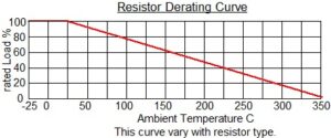
6. Below is one of the Derating Curves for Power Resistors in general, for an individual resistor’s derating curve, please contact us. Different resistor series can have different maximum temperature.
7. We recommend cleaning the Resistor Tab Terminals before use. Do not clean Resistor surface with organic solvents.
8. Do not scratch surface of Resistor with any hard or pointed object.
9. DDR-F and DQR-F series Power Resistors are coated with UL 94V-0 class silicon coating. The Resistors should be installed away from any flammable materials.
10. Silicon coated resistors might emit smoke during initial power loading. It is a normal phenomenon. No smoke will be emitted after loading it 100% for 1-3 hours.
11. If possible, ground the resistor metal mount fixture and/or the metal enclosure.
C. All our Load banks RB3A, RLB3A, RB, DB, RBA, DSR-WB, DSR3-WB, FVRB and RBC series, should be Ground connected below connecting the Load Source and loading the load bank.
D. Adjustable Wire Wound Resistor DSR-F / Rheostat FVR / Rheostat Box FVRB and DSR-WB series application note :
Rheostat and Adjustable Wire Wound Resistor is a kind of wire wound resistor.
It’s performance is bounded by both Ohm’s Law and resistance wire Current carrying capacity.
The function of a rheostat is to deduce the circuit current from the maximum current at the rheostat minimum resistance value to the minimum current at the rheostat rated resistance.
Di. Parameters determination :
1. Rheostat rated Power = (Rheostat maximum load Current)^2 x rated Resistance
2. The maximum load current is determined by the current of an existing application before the adjustable Power Resistor or Rheostat is inserted. This consideration is for Circuit Current adjustment.
3. The maximum loading current is limited by the resistance wire’s current carrying capacity and Ohm’s Law. Loading Current beyond this can damage the adjustable resistor / rheostat.
4. In terms of Rated Power, a smaller Rated Resistance value means the rheostat will have a larger Rated maximum Current capacity.
It is not necessary to buy the standard resistance value.
Most of the times, ordering Customized Resistance rheostat will not affect the cost and lead time.
5. Rheostat minimum resistance value can be calculated with the maximum current and voltage.
6. Rheostat maximum resistance value can be calculated with an acceptable minimum current and the voltage.
7. The workable Power will decrease as the resistance is adjusted to a smaller value.
The workable power at the adjusted resistance is about the ratio of (adjusted resistance) to (the rated maximum resistance of that rheostat) x ( rated rheostat power) or
i.e. in material point of view : Power per Unit Resistance
Dii. Other Application Note :
1. Load Current at the adjusted resistance value =< Rheostat rated Current
2. Load Power at the adjusted resistance value =< Rheostat rated Power
3. Rated resistance value is not the same as an adjusted resistance value.
4. The voltage across Rheostat might need to decrease to avoid over loading the rheostat when reducing the resistance value.
5. A fixed power resistor can be connected in series with the rheostat to protect it from over current damage.
The fixed resistor resistance value is determined by the rheostat maximum load current.
The Resistor power = (maximum load Current)^2 x rated Resistance.
6. The main role of Adjustable Power Wire Wound Resistor DSR-F, Rheostat FVR, Rheostat Box FVRB and DSR-WB is to decrease, not increase, the electrical current in the circuit.
7. The above is for Continuous Load Current – Continuous Resistance range design.
8. For some situations, we will suggest RBA series Adjustable Load Bank.
This Load Power / Current adjustment by preseting steps – discrete resistance values.
Load current is achieved via circuit breakers or power switches at control panel.
Each switch can control a preset resistance value ON/OFF.
With different ON/OFF combination, different load current can be achieved.
For example : 250Vdc with max. current 150A.
The setting can be :
10A, 20A x 2, 50A x 2 = 150A in 5 steps with resolution 10A or
1A, 2A x 2, 5A, 10A x 2, 20A, 50A x 2 = 150A in 9 steps with resolution 1A or
If necessary, we can support some other precision resolution like 0.5A, 0.2A and 0.1A.
The load Current is achieved by load Step adjustment.
e.g. 97A is needed, switch : 2A, 5A, 10A, 10A, 50A is ON
This load bank rated power is 250V x 150A = 37.5kW only.
When compare with rheostat, RBA series load banks, this can be a cost saving option.
Diii. Other application note :
1. For Rheostats, the resistance adjustment is achieved by sliding the metal brusher across the metal resistance material.
In high current, voltage and power condition, there is chance to have flashover among the movable metal parts and resistive material.
We suggest to power OFF the load source across the Rheostat before adjusting the resistance value for High Voltage or High Current situation.
2. Do not touch the Adjustable Resistor / Rheostat surface when it is connected to the power source due to High Resistor Surface Temperature and avoid ELECTRIC SHOCK.
3. We recommend choosing a resistor with a rated power of at least 1.2 to 4 times higher than the actual required loading power if your application requires the resistor to run continuously for 100% duty cycle. This can extend the resistor’s service life and lower it’s surface temperature.
4. There are metal movable parts within the Rheostat. The rheostat has to install in a fixed and level bench to avoid vibration.
5. Salty, dusty, humid, high temperature, vibration and corrosive environment can affect the Rheostat performance.
6. Both above Section A and B application notes are also true for adjustable wire wound resistors.
Dvi. Rheostat Bank FVRB / Adjustable Load Bank DSR-WB options :
1. Meter : Ammeter, Voltmeter, Wattmeter, Ohm meter and Temperature meter
2. OverCurrent protection
3. OverVoltage protection
4. Thermal protection
5. Cooling Fans system